Lateral resistance through vertical diaphragms or braced frames. Knee braces as seen here for lateral have no code.

Moment Resisting Timber Connections Ppt Video Online Download
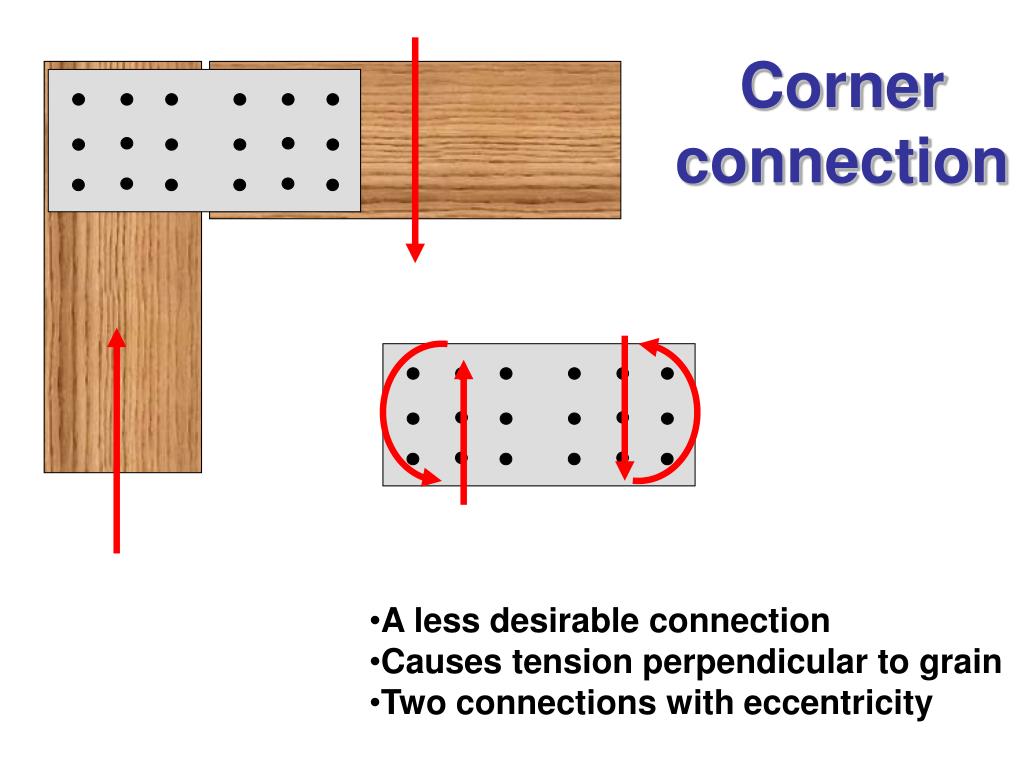
Not intended in the design and the connection could fail prematurely because it may not be able to provide the needed moment resistance as they are governed by the tension perpendicular to grain and longitudinal shear strengths of timber.
. This gives a design shear force and a bending moment Figure 4. Create a new moment-resisting connection component. Office areas y 2 TABEC0_BSpsi.
Examples of diff erent truss sy stems wher e connections have been used to combine. Allowable loads on one bolt in seasoned wood loaded at both ends in normal duration. The most common timber material used glued laminated timber glulam was introduced.
Determine allowable stresses given in this example. In this post we are going to look at a design example of beam splice connection beam to beam connection using steel plates. Example IIB-1 Bolted Flange-Plate FR Moment Connection beam-to-column flange Given.
Find Max Shear Moment Simple case equations Complex case - diagrams University of Michigan TCAUP Structures II Slide 43 of 52 Design Example 2. Figure 2 illustrates the loads that can cause cleavage as a result of tensile loads perpendicular to the grain. 8the engineering principles of open frame forms of construction including post and beam and rigid frame construction were presented.
Figure 62 gives an example of a beam to column connection and its moment rotational diagram. Remember that the adhesive sticking the straws together is weak. Loading at centre of the connection.
The design strength of a moment connection may be full- strength ie. Spacing of Screws in Box Beam made from Rectangular Wood. Pinned connections also referred to as simple connections are free to rotate under load and are assumed to resist no moment only shear forces.
The first part of the Guide presents the terminology concept and design of timber diaphragms with their connections to the lateral. As is the moment. Bending Stress and Shearing Stress in Timber Beam.
Journal of Wood Science nr. Let us design a bolted beam splice connection for a UB 533 x 210 x 101 kgm section subjected to the following ultimate limit state loads. 4 Timber connectors 5 Connection plates 6 Specification of connections 7 Eurocode Design of Dowel Type Fastener 8 Other design considerations 9 Connection calculations examples 10 Comparing C16 vs C16 timber connections 11 Summary.
This joint should be able to transmit bending shear and axial forces. Rules and standards change in pace with the development of society why a publication of this type has to be reviewed regularly. In Engineering Bulletin No.
Instructional Material Complementing FEMA 451 Design Examples Timber Structures 13 - 9 Post and Beam Space frame for gravity loads. Dont have a code handy and this was a number of years ago. Group Species of Philippine Woods.
I remember seeing in the EuroCode timber design a significant section on moment connections for timber construction. CatCatagory 030 Service class C S SELEC5_BSmod. DESIGN EXAMPLES Comparative Shrinkage of Sawn Timber and Glulam Beams 499 Simple Beam Design 500 Upside-Down Beam Analysis 502 Tension-face Notch 504 Compression-face Notch 505 Sloped End Cut 507 Beam Stability Effective Length Method 509 Beam Stability Equivalent Moment Method 512 Cantilever Beam Stability Equivalent Moment.
48 2002 Japan Wood Research Society Inst. 5 Final deflection Catagory SELEC0_BSpsi. The timber section size is often determined by the strength of the section remaining after drilling holes for bolts or dowels or by the spacing requirements for the fasteners rather than the load-carrying capacity of the timber.
Mat T 2 k def TABEC5_BSmod. ScC S 080 w finG instGw 1 k def 550 1 080 990 mm w. The moment capacity of the connection is equal to or large than the capacity of the.
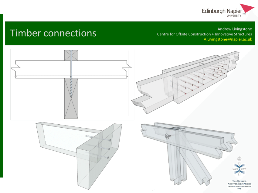
Of Wood Techn Akita Japan. The derivation of design clauses for nailed and bolted joint in Eurocode 5 In Proceedings of paper CIB-W18 paper 19-7-6 Florenze 1986 Yasumura M. Andrew Livingstone Timber connections Centre for Offsite Construction Innovative Structures ALivingstonenapieracuk Content 1 Introduction 2 Nails Screws Bolts Dowels 3 Glued joints 4 Timber connectors 5 Connection plates 6 Specification of connections 7 Eurocode Design of Dowel Type Fastener 8 Other design considerations 9 Connection calculations.
In statically determinate frames a partial strength connection adequate to resist the design moment is satisfactory. In tests the first part of the moment rotational diagram representing the stiffness. Moment Connections in Timber Introduction Structural connections are categorized as either pinned connections moment connections or semi-rigid connections.
Floor Diaphragms in Timber Buildings presents designs for flexible and rigid diaphragms including structural elements and connectionsIt covers the terminology concept and design of timber diaphragms as well as a design example. This means that the centre of the connection will be at a distance of 1580 mm from the right end of the cantilever 1750 - 80 - 60 - 30. And Sawata K Determination of embedment strength of wood for dowel-type-fasteners.
The application of moment-resisting connections in timber structures offers designers the potential to make the structural system as efficient as. EXAMPLES TO EUROCODE Timber Design to EN 1995 BS EN Page. The drinking straw analogy for timber works well when one is designing connections.
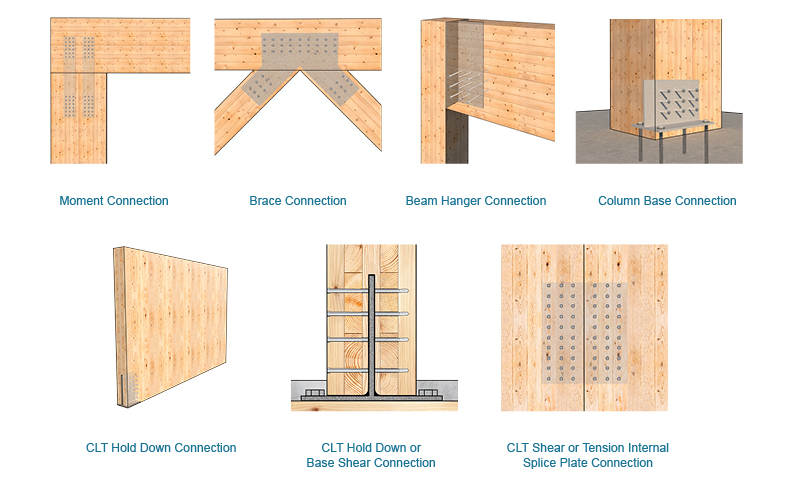
Connections are an essential part of any structure and in timber structures they are often the most critical part of a design. It was elegant in that the the connections were bolted with the bolt pattern being circular. If the frame is statically indeterminate the connections must have sufficient ductility to accommodate any inaccuracy in the design moment arising for example from frame imperfections or settlement of supports.
Maximum Concentrated Load a Box Beam Can Carry. Timber Connections Design theory to Eurocode 5 a 1 hour CPD. Any connection which tends to cleave the wood will of necessity be weak.
Moment continuity at joint typically only if member is continuous through joint. The two weakest strength properties of wood. Design a bolted flange-plated FR moment connection between a W1850 beam and a W1499 column flange to transfer the following forces.
This Engineering Bulletin introduces the construction and connection details appropriate to open frame construction. 4 Design of timber structures Volume 3 Preface This is the second revised edition of Design of timber structures Volume 3 Examples published in 2015. Load wood span Reqd.
Pdf Timber Connections Design Theory To Eurocode 5

Moment Resisting Timber Connections Ppt Video Online Download
2
Designing With Internal Knife Plates Mass Timber Connections Mtc Solutions

Seismic Design And Performance Evaluation Of Self Centering Timber Moment Resisting Frames Sciencedirect
Ppt Moment Resisting Timber Connections Powerpoint Presentation Free Download Id 442871
2
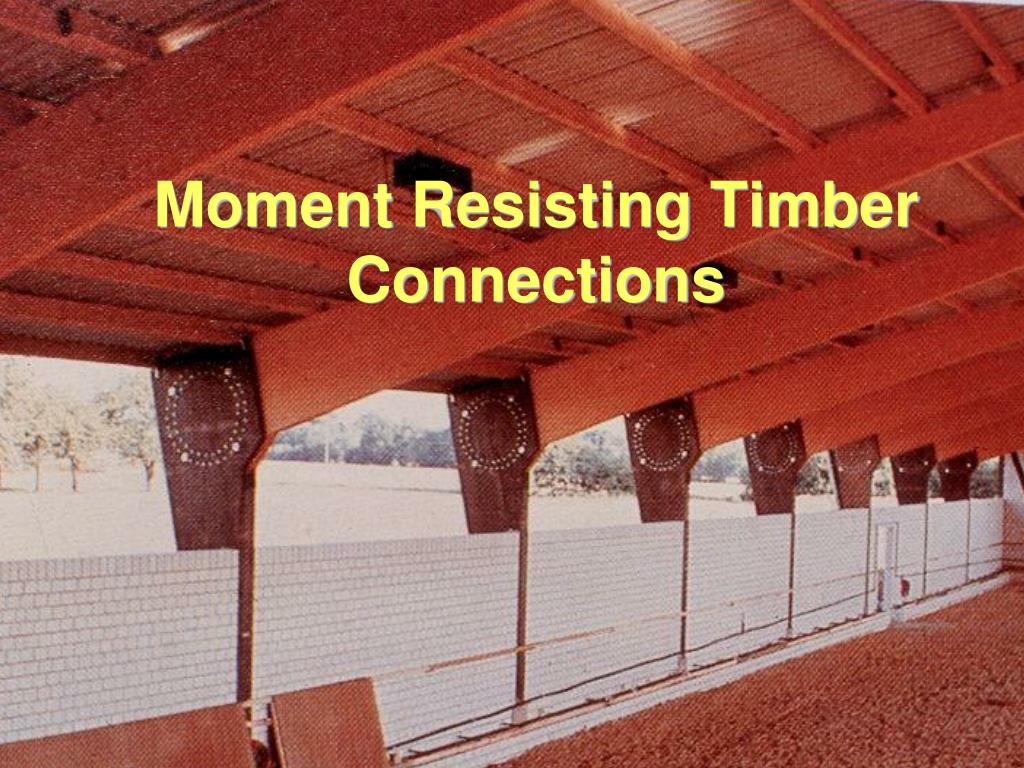
Ppt Moment Resisting Timber Connections Powerpoint Presentation Free Download Id 442871
0 comments
Post a Comment